
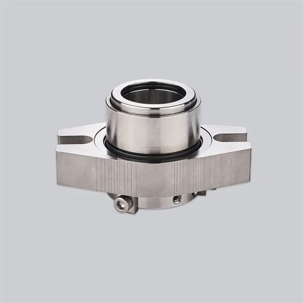
Proper installation is the single most important factor in cartridge mechanical seal lifespan and leak-free performance. Unlike component mechanical seals that require full on-site assembly and alignment, cartridge seals come pre-assembled and pre-calibrated at the factory, drastically reducing human error. Even so, following a standardized installation sequence is critical: misaligned gland faces, uneven bolt torque, or premature removal of centering clips are the top causes of early seal failure.
Below is a complete, industry-standard procedure for setting a cartridge mechanical seal, including pre-installation checks, step-by-step mounting, and post-install validation, aligned with API 682 and API 610 specifications.
Key Takeaways
- Always complete lockout/tagout and full system pressure relief before starting any pump seal work.
- Verify shaft runout, surface finish, and stuffing box squareness before mounting the seal.
- Tighten gland bolts in a cross (star) pattern across three torque stages to keep seal faces perfectly parallel.
- Critical rule: Fully tighten drive collar set screws before removing centering clips to preserve factory-set spring compression.
- Finish with a manual shaft rotation check and static hydrostatic test before putting the pump into service.
Cartridge Mechanical Seal Pre-Installation Preparation
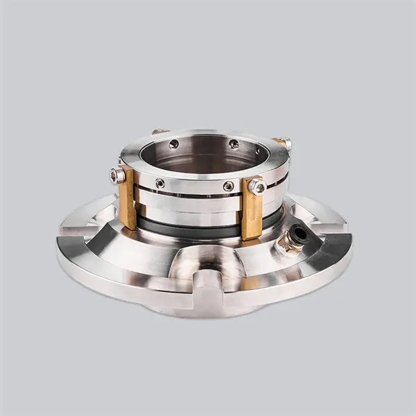
Complete all pre-checks before unpacking the seal to avoid rework and safety hazards.
Safety Lockout & System Depressurization
- Lock out and tag out the pump power source to prevent accidental startup.
- Fully relieve system pressure and drain all process fluid from the pump casing and stuffing box.
- Secure the pump shaft to prevent unintended rotation during installation work.
Shaft Condition & Runout Verification
Damaged or misaligned shafts are the leading cause of premature O-ring and seal face wear.
- Inspect the shaft sealing surface for scratches, burrs, or corrosion — any raised defects can tear O-rings and cause leaks. Polish or file down uneven edges as needed.
- Measure shaft radial runout with a dial indicator:
- Per API 682 standard: Maximum 0.002 inches TIR (total indicator reading)
- Per API 610 standard: Maximum 0.001 inches TIR
- Confirm shaft surface finish matches elastomer requirements:Seal SurfaceRecommended Surface Finish (Ra)Dynamic O-ring sliding surface0.2 – 0.4 µmStatic O-ring groove surface0.4 – 1.6 µm
Stuffing Box Dimensional Check
Confirm the stuffing box face is perpendicular to the shaft to avoid cocking the seal:
- Maximum allowable perpendicular runout: 0.005 inches per inch of shaft diameter (0.005 mm per mm for metric sizes).
- Verify stud spacing and stuffing box depth match the seal gland dimensions.
Install the Cartridge Mechanical Seal
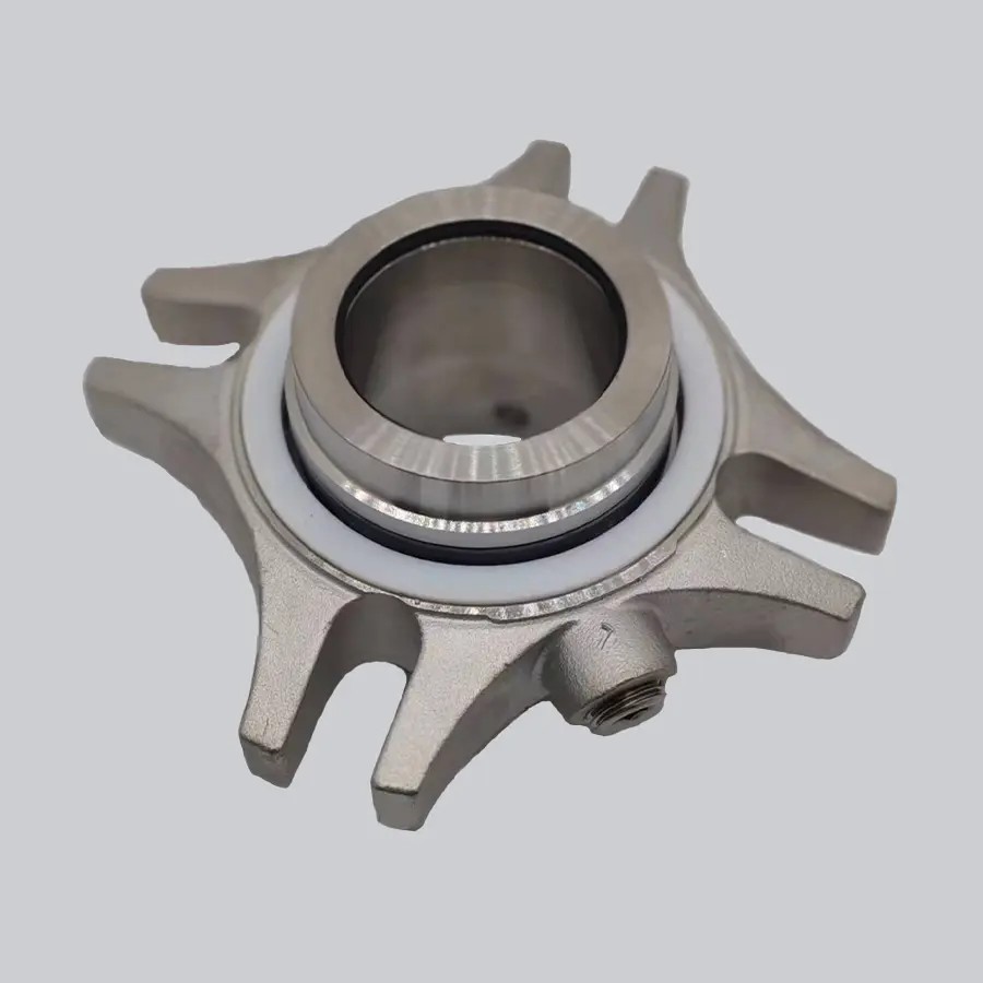
Lubricate O-Rings & Shaft
Proper lubrication prevents O-ring scuffing and cutting during sliding installation.
- Apply a thin layer of compatible lubricant to the sleeve O-rings and gland gasket.
- Silicone-based lubricants are compatible with EPDM and FKM elastomers (e.g., DuPont 111, Parker O-ring lubricants).
- Clean water or mild soapy water is a safe, universal option for all elastomer types.
- Never use petroleum-based lubricants on EPDM rubber — they cause rapid material degradation and premature seal failure.
- Wrap sharp shaft features (keyways, threads) with protective tape to prevent slicing O-rings during assembly.
Slide the Cartridge Assembly Onto the Shaft
- Guide the full seal assembly smoothly onto the shaft, sleeve end first.
- Push the unit into the stuffing box until the gland flange sits flush against the box face.
- Do not strike the seal with a metal hammer or hard tool. Impact can crack silicon carbide seal faces and cause immediate failure. Use steady, even hand pressure only.
Align the Gland with Pump Studs
- Line up the gland bolt holes/slots with the stuffing box studs.
- Align flush, quench, or drain ports to match the piping layout per the equipment drawing.
- Ensure the gland sits flat and square against the stuffing box face with no binding or tilting.
Torque Gland Bolts in a Cross Pattern
Uneven gland bolt torque is the most common cause of seal face misalignment and uneven wear. Use a calibrated torque wrench and follow this three-stage star/cross tightening sequence:
| Tightening Pass | Target Torque | Pattern |
|---|---|---|
| 1st Pass | 30% of full rated torque | Star / cross pattern |
| 2nd Pass | 60% of full rated torque | Star / cross pattern |
| 3rd Pass | 100% of full rated torque | Star / cross pattern |
| Final Verification | 100% full torque check | Circular sweep |
💡 Maintenance Tip: Clean gland stud threads with a wire brush before tightening. Dirty or corroded threads give false torque readings and result in uneven clamping force.
Tighten Drive Collar Set Screws
The drive collar transfers rotational force from the shaft to the rotating seal face, and locks in the factory-calibrated spring compression.
- Wipe the shaft surface clean of dust and rust to ensure a secure, slip-free grip.
- Tighten set screws evenly in an alternating pattern:
- Finger-tighten the first set screw.
- Rotate the shaft to access the opposite screw and tighten to 50% torque.
- Work around the collar until all screws reach full specified torque.
⚠️ Critical Safety Rule: Always fully torque set screws BEFORE removing centering clips. Removing clips early releases spring tension, erases the factory-set working length, and causes permanent seal face damage.
Remove Centering Clips & Spacers
Centering clips hold stationary and rotating seal components in perfect alignment during shipping and installation. They must be removed before pump startup.
- Loosen clip retaining screws and slide the clips straight out from the gland body.
- Store clips in a labeled, dedicated location — they are required for future seal removal and re-installation.
- Double-check that no clips, spacers, or packaging materials remain in or around the seal assembly.
Testing and Validating a Cartridge Mechanical Seal After Installation
Always complete these checks before returning the pump to service.
Manual Shaft Rotation Check
- Turn the pump shaft by hand to verify free, smooth rotation.
- Smooth, even turning: Confirms proper alignment and face spacing; proceed to piping connection.
- Binding or heavy rubbing: Indicates a cocked gland or misaligned faces. Re-check gland torque and shaft straightness before proceeding.
Connect Flush & Auxiliary Piping
- Attach flush, quench, or drain lines to the corresponding gland ports.
- Apply thread sealant or tape correctly to prevent port leaks.
- Ensure piping does not place side load on the gland, as this can misalign the seal over time.
Hydrostatic Leak Pressure Test
- Fill the pump casing with clean test fluid.
- Apply static test pressure per equipment specifications and hold for the required duration.
- Inspect the gland, shaft, and connections for signs of leakage.
Leading mechanical seal manufacturers like Victor produce premium cartridge seals with precision-machined silicon carbide faces and strict geometric tolerances, helping achieve reliable zero-leak performance during static pressure testing when properly installed.
FAQ
Why do you leave centering clips on during installation?
Centering clips hold the rotating and stationary seal components in perfect alignment, and maintain the factory-set spring compression during mounting. Removing them early causes the seal to lose its calibrated working length, leading to face damage and leaks.
What happens if centering clips come off too early?
Early clip release immediately drops spring tension and shifts the seal out of its designed operating position. This can chip or crack seal faces, and will almost always cause leaks at startup. The seal will need to be fully re-set or replaced.
How do you check shaft runout before installing a seal?
Mount a dial indicator on the pump casing with the tip resting on the shaft sealing surface. Rotate the shaft slowly by hand and record the total variation (TIR). For most industrial pump applications, runout must stay below 0.002 inches.
Why are cartridge seals more reliable than component seals?
Cartridge seals are fully assembled and tested at the factory, eliminating the most common installation errors related to spring setting and face alignment. This results in much lower failure rates during installation and longer average service life.
Final Thoughts
Cartridge mechanical seals simplify installation dramatically compared to component seals, but precise, step-by-step execution is still required to achieve maximum service life. By following thorough pre-installation checks, using a cross torque pattern, and observing the critical set-screw-first rule, maintenance teams can drastically reduce early seal failures and extend pump uptime.